_THE FUEL TANK
THE FUEL TANK
Intro
As a continuation of the techniques learnt over the first assessment of creating the bowl, torus, tray and blister, the second assessment would utilise these skills, together with basic comprehension of digital software including Slicer, Rhino of Grasshopper, as well as interdisciplinary learning, to help create our fuel tank of choice.
In an initial team of 7 members including Selina Chen, Monique Robinson, Eddie Song, Daniel Gioia, Matthew Zeng, Pete Phuah & myself we began by working together to create a 1:1 scale
template replicating a 'custom' motorcycle fuel tank through use of various softwares.
Later we divided into a teams of 4 & 3 where we were able to split the task of making the fuel tank into individual pieces. For my group i teamed up with Monique Robinson, Selina Chen & Eddie Song.
As individuals, we then created an aluminium skin to adhere to a our selected quarter to match it's contours.
_
Beginning with the final product i will then follow with a step by step guide of the projects processes.
Final product

Materials Required:
Aluminium Sheet
Paper
Masking Tape
Scissors
Measuring Tape
Marker Pen
Nylon Mallet
Planishing Hammer
Mallet
Sandbag
Dolly
Vice
Tinsnips
Guillotine
Straight File
Rounded File
English Wheel
Stump
Shrinker
Metal Polish
Rag
Rhino Software
Grasshopper Software
Laser Cutter
A step by step procedure:
Step #1
The first step in creating the custom fuel talk was to create a 1:1 replica plywood mould, by using Slicer, Rhino & Grasshopper.
Using the provided 'custom tank' file in Rhino we would create a 3D image of our model tank (image 1). However before we could import the image into 360 slicer, we had Russell assist with cleaning up with file as it appeared broken. To do this the program Grasshopper was used (image 3).
Within slicer we were able to automatically set out the templates and amend the thickness of our joints. For this, we chose to go with 3.8mm gaps which was suggested to us by other groups who had already tested with 3mm plywood. Another awesome thing about slicer was that it automatically separated the sections into various quantities of x & y planes ( x=horizontal & y=vertical.
In slicer the model was separated into different sections with horizontal planes marked x and vertical planes marked y (see image 9)
If we were to re do this step -
I would reconsider the thickness of plywood used (as the 3mm quite brittle) and shorten the space between each slice (as it wasn't quite solid enough).


Step #2
Before proceeding with laser cutting, the file was edited to allow for correct cut lines (red 255) and etch lines (blue 255). Our etch lines would provide a guide to assembling our model later. All lines were set to 0.001 thickness too. Using 3mm plywood for each panel we began cutting out our 7 sheets of templates!
Once the pieces were all cut we organised them into x and y pieces before we began to assemble.
On first attempt we began by constructing from the bottom up, however we ran into issues when the model would became too rigid and parts started snapping.
This meant we needed to reevaluate our construction method. Lucky for us Eddie Song was a skilled model maker and recommended a second approach. So this time we began by assembling the bottom x component and middle y component, before working our way outwards with the largest pieces. This level of distribution allowed an even spread of tension. Small fragments which we were unsure of were left until last to solve. This method seemed to work a charm with the added help of some glue holding everything together as well. 2 hours later we were done!
By creating this scale model, we were able to improve our understanding of digital functions as well as provide ourselves with a base which would help determine how the petrol tank be broken down.
If we were to re do this step -
I would perhaps use 5mm plywood as the 3mm was too thin. Causing damage and loss of parts.


Step #3
The next step involved cutting a paper template to assist with creating our aluminium shape. As the properties of aluminium and paper are similar, the template provided a useful tool to indicate where the sheet metal would need to be shrunk and stretched.
By applying strips of paper across the model, and marking out the location of our 4 components, we created our 'dressmaker' pattern.
Despite being advised that the petrol tank was best split into 3 components (top piece and two side pieces) we decided to split it down the middle, giving us two top pieces and two side pieces.
On the first observation we thought the cut line would be best positioned beyond the curve, but later learnt cut lines are best positioned along the curve, allowing for cleaner joining and easier shaping.

Step #4
Once the pattern was cut and removed, we used each component to indicate just how much aluminium material we would need to use. By tracing around the paper templates (see image 18) we could ensure enough material was cut. To ensure accuracy the paper was flattened out, and a 10mm scope was left around the perimeter. Furthermore, rid lines were drawn (see image 18-20) indicating levels of gradients. The excess would be cut later, allowing room for error.
Next we used a metal guillotine to cut our shape out. Here the tight corners and edges were finished with tinsnips and file. As the edges didn't need to be finished until the final part of the process, the edges were only roughly filed down in precaution of safety against harmful edges.


Step #5
Now we were able to start shaping!
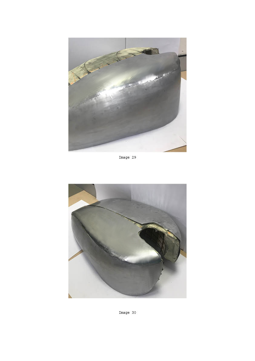
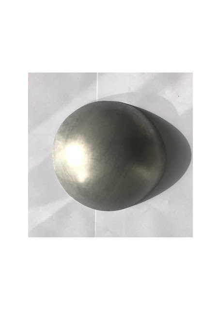
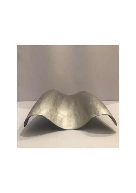
Here, I began by gently working with a nylon mallet, sandbag and stump. Working between the two, i began to shape my edges. Soon i moved on with a planishing hammer on both a sandbag and steel dolly to help flatten the top part of my shape as well as shape the contours i needed.
This process was very time consuming as i worked back and fourth between each method trying to perfect the shape. To form the edges and longitudinal curve i used the shrinker, however i found this to distribute metal to other places and distort my shape quite easily. With this issue, i found it really difficult to form the perfect replica fit.
To help smooth out the imperfections left by planishing hammer and nylon mallet, i used the english wheel (see image 25). However, this distorted my object even more, as it quickly stretched too much causing the aluminium to curve where it should have stayed flat!
Finally after hours of working & reworking my piece, i had to leave it as it was driving me insane.. later discovering that the best method would have been to first curve the shape longitudinally, only to shrink the edges last.
>.<


REFLECTION:
Despite previously feeling confident in metal shaping, this task, proved much more difficult. Although the tanks shape appeared quite simple at first, the smallest changes caused major ripple effects and therefore made this project quite time consuming. However, it was due to these unprecedented effects that i was actually able to develop a better understanding of working with aluminium.
As a student of interior architecture, the programs used in this task were all new to me. The brief use of these softwares have provided me with basic information as to how these programs are used which i would consider revisiting in future.
Comments
Post a Comment